This page is intended to demonstrate implementing SIRC using JALv2. I will take you through the process of developing an IR based remote control system using JALv2. This process will demonstrate the use of some of the standard libraries, protocol interpretation and how to implement it in software. We will build both transmitter and receiver circuits, the receiver will be adaptable to basically control any device you would like to control.
To start with, let's define SIRC, it is the protocol used by Sony for remote control of their products. It is a PWM-based serial data transfer protocol. If you search on the internet for Sony SIRC you will find many pages that describe the protocol. The one I like best is www.sbprojects.com/knowledge/ir/sirc.htm which states "The SIRC protocol uses a pulse width encoding of the bits. The pulse representing a logical "1" is a 1.2ms long burst of the 40kHz carrier, while the burst width for a logical "0" is 0.6ms long. All bursts are separated by a 0.6ms long space interval. The recommended carrier duty-cycle is 1/4 or 1/3."


"The picture above shows a typical pulse train of the SIRC protocol. With this protocol the LSB is transmitted first. The start burst is always 2.4ms wide, followed by a standard space of 0.6ms. Apart from signalling the start of a SIRC message this start burst is also used to adjust the gain of the IR receiver. Then the 7-bit Command is transmitted, followed by the 5-bit Device address. In this case Address 1 and Command 19 is transmitted. Commands are repeated every 45ms(measured from start to start) for as long as the key on the remote control is held down."
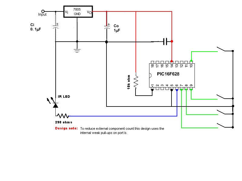
We now have all the information we need to begin designing a circuit and writing code to receive and decode SIRC transmissions. We will begin by using either a SONY branded TV remote or a "universal" remote programmed to act as a Sony remote. Let's start with the components, we will need an IR receiver, a PIC microcontroller, resistors, capacitors, a power supply, a breadboard, an LCD display, some LEDS. For the IR receiver I will be using a TFM5360 from The Electronics Goldmine, item G14384 but any receiver suitable for detecting 36 kHz to 40 kHz IR signals should work. I will prototype with a 16F628 using the internal oscillator and a HD44780 based LCD display in 4-bit mode. For easy reference the schematic diagram will be provided as a link in the column to the left, as will the source code. This way if you are using a tabbed browser (and who isn't these days) you can open them in another tab and continue to read from this page. A quick note to all you critics out there about the schematics I will be posting, I am well aware of the available schematic drawing software available but I am doing this because in many cases the symbol I use (especially for ICs) will more closely resemble the physical device than the symbol that say EAGLE uses. Remember, these diagrams are for illustrative purposes not PCB layout.
Receiver
If you open the file SIRC LCD receiver source code you will see that the first 43 lines are a description of what the file does and some background information on the topic. It is always a good idea to document the purpose of any code you write for future reference. Six months or a year from now you may not remember what it was meant to do. Next you will see we declare the chip we are going to be using, the oscillator frequency and type, and other options for the chip itself. Notice we are using the internal oscillator of the PIC and set the speed at 4 mHz, the speed of oscillation will be used by the compiler and included libraries to calculate delays so that a 10 millisecond delay is a 10 millisecond delay whether you use a 4 mHz oscillator or a 20 mHz oscillator. After setting up the PIC we then declare any needed constants or variables we will be using, variables and constants declared here are global in nature and can be accessed from other procedures or functions used in your program. You will notice that we also try to use names that will have meaning to us when we see them later in our code. After declaring our variables we then setup our input and output pins and include any needed support files. Before you can use any procedures or functions you have to "declare" them, this simply means writing them as you can see in the source code. Finally we arrive at our main routine where we disable the analog functions of any pins we are planing to use as digital i/o pins, this is important because their default is to be analog pins and many times this has caused headaches trying to figure out why something is not working as it should. We also initialize our LCD display and clear the screen. As will be the case much of the time our main routine doesn't have much "meat" to it.
The first thing you will notice is that we have an if loop looking for IR_pin to go low, now this may seem strange since our description of the protocol above shows everything going high, this is because the signal gets inverted by the IR receiver, highs are lows and lows are highs after reception, therefore we look for the pin to go low signifying we have received an IR signal and then we call our procedure Get_SIRC to interpret what we have received.
As you can see the first thing we do is declare any needed variables, variables declared in a procedure or function are local in scope and are not accessible from any other place in the program. Let's ignore the 2 lines beginning with the compiler directive "asm" for a little while, their existence will be explained shortly. That takes us to a while loop where we keep reseting the value of lTime to zero as long as IR_pin is high. At first glance you might wonder why we are doing this, well things happen pretty fast in the real world and from the time we jumped from our main routine to our procedure our pin may have changed state many times and to decode the protocol we need to find a "start burst" Now once the pin goes low we have a loop that does a couple of things as long as the pin is low. First in increments lTime by 1 and then waits 200 microseconds, if at the end of this time the pin is still low it repeats these actions until the pin goes high. At this time it compares the value of lTime to 10 and 14. Why these values you ask, well we are attempting to detect a valid "start burst" and if you will recall a valid "start burst" is 2.4 milliseconds of IR pulses, 10 X 200 = 2000 and 14 X 200 = 2800, 2000 microseconds = 2 milliseconds and 2800 microseconds = 2.8 milliseconds, this gives us a "window" for a valid "start burst" of 2 to 2.8 milliseconds to allow for leeway in frequency variations. Now we will get back to the "asm" statements we skipped earlier. JALv2 has no native "goto" command but with out a "goto" we would not be able to restart our check for a valid "start burst" without executing all of the code in our procedure, returning to the main loop, executing all of the code in it until we looped back around to where we checked for IR_pin going low, thus sending us back to Get_SIRC. Not very efficent is it ?
Thankfully Microchip assembler does have a "goto label" command that saves the day. This is how it works, the compiler directive "asm" tells the compiler that what follows is an assembler statement. We first declare a local label "StartLook" in assembler, and then we place it in our JAL code at a specific location with the asm StartLook: statement. Later, in the if statements we use a goto StartLook to jump back to this location if we do not detect a valid "start burst". This feature is documented in the JAL User's Guide in section 14. Assembly.
Now that we have detected a valid "start burst" we can start looking for the seven 1's and 0's that make up our command. (Remember from our description of the protocol that the "IR command" is sent LSB first with the 7 bits of the command code first then the 5 bits the device code). First we have a for loop that of course loops seven times, inside that loop we first shift ir_cmd right 1 bit position, initially this will not make any difference because ir_cmd is equal to zero "00000000" and we are only interested in 7 of the 8 bits. We then reuse the lTime variable to keep track of loop time as before and again we keep resetting it to 0 as long as the pin is high. Once the pin goes low we again increment lTime by 1 and delay 200 microseconds, if at the end of 200 microseconds the pin is still low we repeat the loop until the pin goes high. Once the pin goes high we compare the value of lTime to 6, if lTime is 6 or more then we have detected a "1" (Remember from our protocol description a "0" is 600 microseconds of carrier and a "1" is 1.2 milliseconds or 1200 microseconds of carrier) That makes sense you say but what is this ir_cmd = (ir_cmd | 0b01000000) stuff, well this is the easiest way of putting a "1" in bit position 7 of ir_cmd. That simply means ir_cmd is equal to the previous value of ir_cmd bit-wise OR'd with the binary equivalent of decimal 64 which is bit 7 on and all other bits off. After this operation is performed (if needed) we return to the top of the loop where all bits are shifted right 1 position. Maybe a visual representation will help. By the way, the 0b is how JAL designates a binary number, so now for the visual aid. The bold italicized bit is the bit of interest.
ir_cmd = 0b0000_0000
1st time thru loop shift right 1 position 0b0000_0000
but doesn't matter since all bits are zero
we detect a "1" and perform the OR so now we have 0b0100_0000
2nd time thru loop shift right 1 position 0b0010_0000
we detect a "0" so no OR is performed
3rd time thru loop shift right 1 position 0b0001_0000
we detect a "1" and perform the OR so we have 0b0101_0000
4th time thru loop shift right 1 position 0b0010_1000
we detect a "0" so nor OR performed
5th time thru loop shift right 1 position 0b0001_0100
we detect a "0" so no OR performed
6th time thru loop shift right 1 position 0b0000_1010
we detect a "0" so no OR performed
7th time thru loop shift right 1 position 0b0000_0101
For ir_add we basically perform the same operations only our loop is only 5 times and we OR with 0b00010000 instead of 0b0100000. After these actions are performed we assign the values of ir_cmd and ir_add to the global variables my_cmd and my_add and then return to our main program where the values are displayed on the LCD display. This pretty well covers the reception and decoding of the SIRC protocol. Stay tuned for demonstrations on how to control real world devices with this info and how to make your own transmitter.
Transmitter:
As we set out to build an SIRC transmitter we will need to do a little background work. Let's look at our earlier graphic concerning the make up of a "1" and a "0".

Remember that the 600 microsecond(us) and 1.2 millisecond(ms) periods are bursts of 38 kHz pulses and the recommended duty cycle for the carrier is 1/4 (25%) or 1/3 (33%). How do we get these pulses you ask, well we are going to build them in software. First we must determine the period of our waveform, if you recall from your basic electronics classes there is a relationship between frequency and period, it is :

Plugging our numbers into this equation we get 1/38000 = .000026 seconds for a period of 26 microseconds. Now to figure our duty cycle we simply divide by 4 or 3, to conserve power let's use 4. 26 divided by 4 equals 6.5 so let's just use 6, and 26 - 6 = 20 so here is 2 cycles of our waveform:

We now have an idea of what our waveform looks like and its period is 26 microseconds. We need 600 microseconds of this waveform for a 0 and 1200 microseconds for a 1. Here's how we generate our waveform, first we make a pin high, delay 6 uS and make it low for 20 uS, this gives us 26 uS of time, we use a little math and see that we need to repeat this 23 times to make a 0 and 46 times to make a 1 so here is our code to generate the 0:
procedure ir_pulse_0 is
for 23 loop pulse_out = high
_usec_delay(6) -- 6 microseconds
pulse_out = low _usec_delay(20) -- 20 microseconds
end loop
end procedure
If you were to compile this and run it on a PIC and measure your
waveform you would see that your waveform is off slightly, this is due
to the overhead inherent in all loops and delays (which are usually
also comprised of loops and nops). This overhead is present in all
languages, even assembler and has to do with how many instruction
cycles a command takes to execute. A goto takes 2 instruction cycles, a
call takes 2 instruction cycles, a return takes 2, etc. As you increase
your oscillator speed the execution time of instrucions decreases but
at 4 mHz 1 instruction cycle takes 1 microsecond. Below you will see a
capture from the CheapLA showing what this waveform ends up looking
like time-wise. I have also measured this with an oscilloscope and
confirm the results.

We now see that we are going to need a little tweaking to get our waveform correct. A little trial and error can get us the values we need and I ended up using _usec_delay(3) to get 6 microseconds and _usec_delay(15) to get 20 microseconds. Now that we can generate a waveform with the correct period we can build or routines to generate a 0, a 1, and the 2.4 millisecond start burst just using loops as shown. above, so we use a for loop that re-iterates 23 times for a 0, 46 times for a 1, and 84 times for the start burst. All that is left now is the 600 microsecond dead time between each bit and after the start burst. So we should have the following procedures, where pulse_out is an alias for the pin we are outputing our waveform on.
procedure ir_pulse_0 is
for 23 loop
pulse_out = high
_usec_delay(3) -- 6 microseconds
pulse_out = low
_usec_delay(15) -- 19 microseconds
end loop
end procedure
procedure ir_pulse_1 is
for 46 loop
pulse_out = high
_usec_delay(3) -- 6 microseconds
pulse_out = low
_usec_delay(15) -- 19 microseconds
end loop
end procedure
procedure ir_pulse_start is
for 84 loop
pulse_out = high
_usec_delay(3) -- 6 microseconds
pulse_out = low
_usec_delay(15) -- 19 microseconds
end loop
end procedure
procedure ir_pulse_deadtime is
pulse_out = low
_usec_delay(600) -- delay 600 microseconds
end procedure
These 4 procedures are the backbone of our SIRC transmitter program as you can see in the source code.
Universal Receiver:
To make our universal receiver I just took the SIRC_LCD program, stipped out the LCD display parts of the code and replaced it with some IF …THEN statements and pin driving statements. I chose the address and command codes for volume up, volume down, channel up and channel down for a television but I could have used any buttons for any device. It is all just a matter of changing the code that the transmitter is programmed to send and the IF …THEN statements in the receiver source code. In the Useful Links column you will find links to all source code, schematics, and a chart of device and command codes.